Rotating machine
AP2-1-INV
Development of Liquid Hydrogen Pump with High-temperature superconducting motor
15:15-15:45 Dec.3
*Tomohito Miura
Torishima Pump Mfg. Co., Ltd.
At the heart of global efforts to achieve carbon neutrality lies the imperative to harness clean energy sources like hydrogen. However, the widespread adoption of hydrogen as a fuel has been constrained by the cost challenges associated with its production and transport.
To reduce transportation costs, it is necessary to transport hydrogen in liquid, which has a small volume (1/800 of that of a gas). Therefore, pumps capable of handling liquid hydrogen are needed at all points in the hydrogen supply chain.
However, liquid hydrogen is difficult to handle because of its extremely low temperature of 20 K under atmospheric pressure and its unique properties of low density, low viscosity, and low latent heat of evaporation. When considering pumps driven by motor that use liquid hydrogen as the working fluid, a particular problem is the low latent heat of evaporation. In other words, the low latent heat of evaporation means that the heat generated inside the motor can easily gasify liquid hydrogen. If a large amount of liquid hydrogen gasifies due to heat loss in the motor, transport efficiency will naturally be reduced.
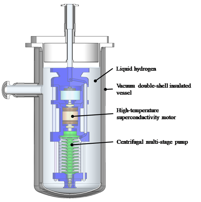
To solve this problem, TORISHIMA PUMP MFG.CO., LTD., in collaboration with Professor Taketsune Nakamura of Kyoto University National University, has developed a centrifugal submerged pump incorporating high-temperature superconductivity.
As shown in Figure 1, this pump is surrounded by a vacuum double-shell insulated vessel and filled with liquid hydrogen. The pump and motor are completely submerged in this vessel. The motor section is kept in a cryogenic environment at all times, allowing the use of high-temperature superconducting motors.
Since the pump is equipped with a high-temperature superconducting motor, gasification of liquid hydrogen due to heat loss in the motor can be minimized. This improves the efficiency of liquid hydrogen transport and contributes to hydrogen cost reduction. This system is very rational in terms of liquid hydrogen transportation.
We have made a prototype pump equivalent in size to that expected in a commercial plant and conducted an operational test using liquid hydrogen at JAXA (Japan Aerospace Exploration Agency)’s Noshiro Rocket Testing Center in March 2024. As a result, a maximum rotational speed of 5,000 min-1, a maximum flow rate of 30.5 m3/hr, and a maximum pressure of 1.6 MPa were achieved, making it the world's largest centrifugal pump for boosting and transporting hydrogen. It is also the first industrial pump equipped with a high-temperature superconducting motor.
This development is a major breakthrough not only in the mass transportation of hydrogen, but also in the industrial application of high-temperature superconductivity.
※This development is supported by a Japanese governmental agency, NEDO (New Energy and Industrial Technology Development Organization) grant "Development of Technologies for Building Competitive Hydrogen Supply Chain".
AP2-2-INV
Design and and assembly of a 250 kW partially superconducting machine
15:45-16:15 Dec.3
R. Dorget1, A. Cipriani2, W. Dirahoui3, *J. Lévêque3, T. Lubin3, S. Ayat1, P. Gning1, J. Labbé1
Safran Tech, Electrical & Electronic Systems Research group, Rue des Jeunes Bois, Châteaufort, 78114 Magny-Les-Hameaux, France1
Absolut System, 3 rue Raymond Chanas, 38320 Eybens, France2
GREEN, Université de Lorraine, F-54000 Nancy, France3
This article presents the superconducting machine demonstrator developed as part of the FROST (Flux-barrier Rotating Superconducting Topology) project, which began in 2020. The demonstrator is a 250 kW partially superconducting machine featuring three key components:
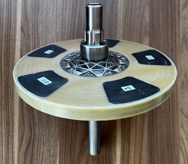
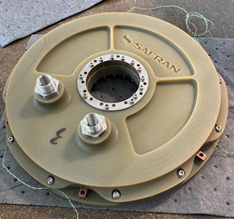
- A rotor made of HTS bulk material (Figure 2).
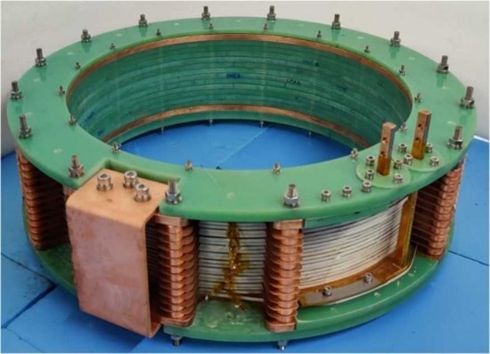
- An HTS static coil, powered by DC current, generating a strong magnetic field within the machine (Figure 3).
- A three-phase armature constructed with Litz copper wire, positioned on both sides of the rotor (Figure 4).
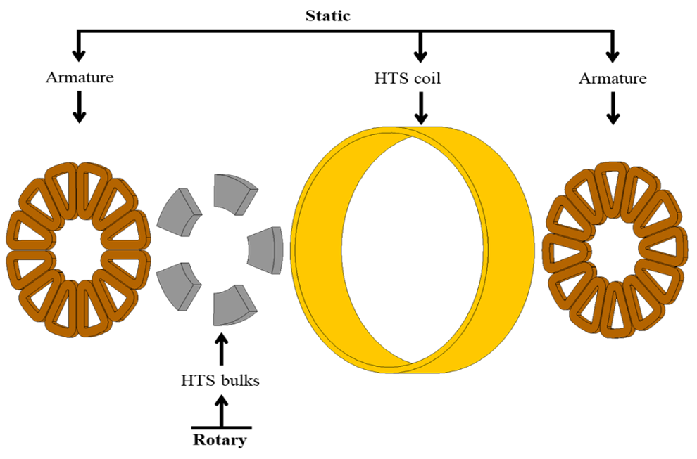
The static part of the inductor, comprising a superconducting coil, produces an axial magnetizing field. The rotating component consists of superconducting bulks placed inside the bore of the superconducting coil. These bulks shield the magnetic flux, resulting in flux density modulation low near a pellet and high elsewhere, so between O and Bmaximum. This system produces a homopolar component of the modulated magnetic flux. The armature uses traditional three-phase windings made of copper, without iron teeth, to enhance performance.
This topology is brushless, as only the HTS bulks rotate, yet it allows for excitation control via the current in the static coil. Additionally, the large magnetic field generated by the HTS enables the machine to be entirely iron-free.
This design has been studied for several decades, with small prototypes primarily in the radial-flux configuration [1]. More recently, the RESUM project (Realization of a Superconducting Motor) resulted in a 40 kW prototype using BiSrCaCuO tapes for the coil and multi-seeded YBaCuO bulks for the rotor [2], completed in 2019. Since 2020, a second prototype has been under development within the FROST project, aiming to achieve 250 kW. Recent efforts have focused on modeling [3] and designing the demonstrator, which was assembled in the summer of 2024. The goal of the FROST project is to scale up from the 40 kW machine of the RESUM project to 250 kW without a significant increase in mass.
To achieve this, we replaced the BSCCO tape in the static coil with a RE_BaCuO tape. Additionally, we modified the shape of the superconducting screen from a round to a trapezoidal form, closely matching the armature coils. Finally, we introduced liquid cooling for the armature.
We will also conduct preliminary magnetization of the superconducting pellets using the static coil. This approach will combine flux modulation with magnetization, eliminating the homopolar component of the magnetic field and allowing it to oscillate between plus and minus Bmaximum, thereby doubling the machine's potential power.
[1] E. H. Ailam, D. Netter, J. Leveque, B. Douine, P. J. Masson, and A. Rezzoug, “Design and Testing of a Superconducting Rotating Machine,” IEEE Transactions on Applied Superconductivity, vol. 17, no. 1, Art. no. 1, Mar. 2007, doi: 10.1109/TASC.2006.887544.
[2] A. Colle, T. Lubin, S. Ayat, O. Gosselin, and J. Leveque, “Test of a Flux Modulation Superconducting Machine for Aircraft,” J. Phys.: Conf. Ser., vol. 1590, p. 012052, Jul. 2020, doi: 10.1088/1742-6596/1590/1/012052.
[3] R. Dorget, T. Lubin, S. Ayat, and J. Lévêque, “3-D Semi-Analytical Model of a Superconducting Axial Flux Modulation Machine,” IEEE Transactions on Magnetics, vol. 57, no. 11, Art. no. 11, Nov. 2021, doi: 10.1109/TMAG.2021.3108632. Example reference – replace or delete
The authors would like to thank the Direction Générale de l’Armement (DGA), the Agence de l’Innovation de Défense (AID), and the Agence Nationale de la Recherche (ANR).
Figure 1. Representation of the active components of a flux modulation machine in its axial flux form.
Figure 2. Picture of the assembled rotor
Figure 3. Picture of the HTS coil
Figure 4. Picture of an assembled cooling carter of the armature
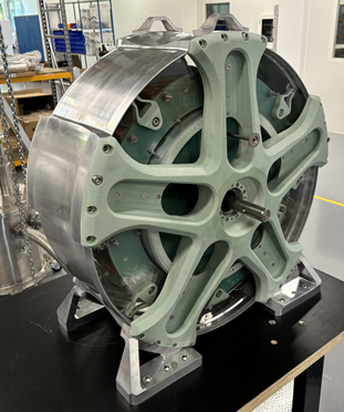
Figure 5. Picture of the assembled machine (without the armature)
Keywords: Axial Field Machine, High Temperature Superconductors, Superconducting Motor, Synchronous Machine
AP2-3-INV
Design and development of 10 kW high-temperature superconducting generation demonstrator cooled by liquid hydrogen
16:15-16:45 Dec.3
*M. Ohya1, A. Ogasahara2, K. Obata2, Y. Terao3, Y. Shirai4, H. Kobayashi5, K. Okai6, O. Sakamoto7
Kwansei Gakuin University, School of Engineering, Sanda, Hyogo, 669-1330 Japan1
Mitsubishi Electric Corporation, Amagasaki, Hyogo, 661-0001 Japan2
University of Tokyo, Kashiwa, Chiba, 277-0882 Japan3
Kyoto University, Kyoto, Kyoto, 606-8317 Japan4
Japan Aerospace Exploration Agency, Sagamihara, Kanagawa, 252-5210 Japan5
Japan Aerospace Exploration Agency, Chofu, Tokyo, 182-0012 Japan6
Sophia University, Chiyoda-ku, Tokyo, 102-8554 Japan7
A hydrogen society is being promoted in Japan, and hydrogen power generation using imported liquid hydrogen is being considered [1]. The economic challenge is the cost of liquefaction [2], and effective utilization of the cold heat of liquid hydrogen is essential. We are developing a liquid hydrogen-cooled high-temperature superconducting (HTS) generator [3]. As shown in Fig. 1, liquid hydrogen is used to cool the superconducting field coil, and the evaporated gas is sent to a hydrogen gas turbine. The system can be built without a refrigerator and has almost zero cooling cost. The New Energy and Industrial Technology Development Organization (NEDO) Leading Research Program (FY2022-2024) was launched, and we have developed a 10 kW /1800 rpm HTS power generation demonstrator. A cross-sectional view of the demonstrator is shown in Fig. 2. Only the field coils were superconducting. Four 300-turn racetrack-type double pancake coils were arranged to form a four-pole rotor and were cooled using liquid hydrogen. The assembly of the demonstrator has been completed and the shipping test results will be reported at the meeting.
[1] Y. Kanehana, 2nd Hydrogen Energy Ministerial Meeting (2019). [2] DOE Hydrogen and Fuel Cells Program Record, No. 19001 (2019). [3] M. Ohya et al., IEEE Trans. Appl. Supercond., 10.1109/TASC.2024.3354697 (2024).
This presentation is based on results obtained from a project, JPNP14004, subsidized by the New Energy and Industrial Technology Development Organization (NEDO).
Keywords: Generator, High-temperature superconductor, Liquid hydrogen
AP2-4
Demonstration test of a system driving two HTS induction/synchronous motors with one inverter
16:45-17:00 Dec.3
*Taketsune Nakamura1, Masaaki Yoshikawa2, Kenji Kawashima2
Department of Electrical Engineering, Graduate School of Engineering, Kyoto University, 1-30 Goryo-Ohara, Nishikyo, Kyoto, 615-8245, Japan1
IMRA JAPAN Co., Ltd 2-36 Hachiken-cho, Kariya, Aichi, 448-8650, Japan2
We have been conducting pioneering researches on the fundamentals and applications of the High Temperature Superconductor Induction/Synchronous Motor (HTS-ISM) [1,2]. In this study, based on our mature development experiences of the HTS-ISMs to date, and with a view to realizing a practical rotating system for the next generation transportation equipment, we conduct rotation tests to drive multiple HTS-ISMs with a single inverter.
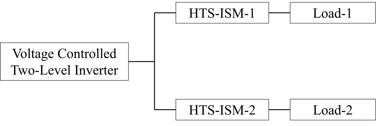
We construct the rotation test system shown in Figure 1 for two 20 kW-class HTS-ISM prototypes that have already been produced. That is, we connect two 20 kW-class HTS-ISMs to a general voltage-controlled two-level pulse-width modulation inverter, and evaluate the rotation characteristics in detail when different loads were applied to each HTS-ISM at a temperature of 77 K. By succeeding the test, it is possible to demonstrate that two motors with synchronous mode can be simultaneously driven by one inverter. Detailed experimental methods and results will be reported on the day of the presentation.
[1] T. Nakamura, M. Yoshikawa, T. Terazawa, K. Matsuki, Y. Gao and T. Kiss, "Development of 50-kW-Class High-Temperature Superconducting Induction/Synchronous Motor with Continuous Drive Characteristics from Room Temperature," IEEE Transactions on Applied Superconductivity, vol. 33, no. 5, 5200205 (5pp) (2023)
[2] T. Nakamura and Y. Ogama, "Relationship between the Induced Voltage of a Rotor Bar and the Rotation Characteristics of a High-Temperature Superconducting Induction Motor," Journal of Applied Physics, in press.
We would like to express our gratitude to J. Matsuura and T. Ogasa for their assistance with the experimental set-up at Kyoto University. This study was supported by JSPS KAKENHI (grant number 22H01471).
Figure 1. Schematic diagram of one inverter - two motor drive system using HTS-ISMs.
Keywords: HTS induction/synchronous motor, One inverter-two motors system, Transportation equipment
AP2-5
Numerical Study of a Direct Drive Generator for Wind Turbine with and without HTS Windings
17:00-17:15 Dec.3
*Shuangrong You, Hongye Zhang, MARKUS Mueller
The University of Edinburgh
High-temperature superconductors (HTS) show potential advantages in generator design by enabling higher power density and more compact generator size. However, incorporating HTS windings necessitates a cryogenic system, which can increase costs, add weight, and reduce overall generator efficiency. Therefore, investigating AC loss in HTS windings is crucial, as the loss largely determine the cryogenic requirements. In this work, we have numerically investigated AC loss in a MW-class modular wind turbine generator consisting of 176 rotor poles. Each 4-pole group serves as a modular unit to facilitate easy installation and removal. Finite-element method (FEM) modelling was applied using COMSOL Multiphysics to build generator models with and without HTS windings.
Four designs were analyzed in this study. Design-1 follows a conventional structure and serves as a reference, utilizing permanent magnets for the rotor and copper windings for the stator. Design-2 and 3 incorporate partial HTS structures. Design-2 replaces the stator copper coils with HTS windings, while Design-3 substitutes the rotor permanent magnets with HTS windings. Design-4 features a fully HTS design, with both HTS rotor and stator. Dynamic analysis of induced voltage in the armature windings and AC loss in the HTS windings was conducted using moving meshes. Simulation results indicate that both partial and fully HTS design offer higher power density compared to the conventional design. However, managing the heat generated by AC loss in HTS armature windings remains challenging, even at low rotating speeds in cryogenic environments.
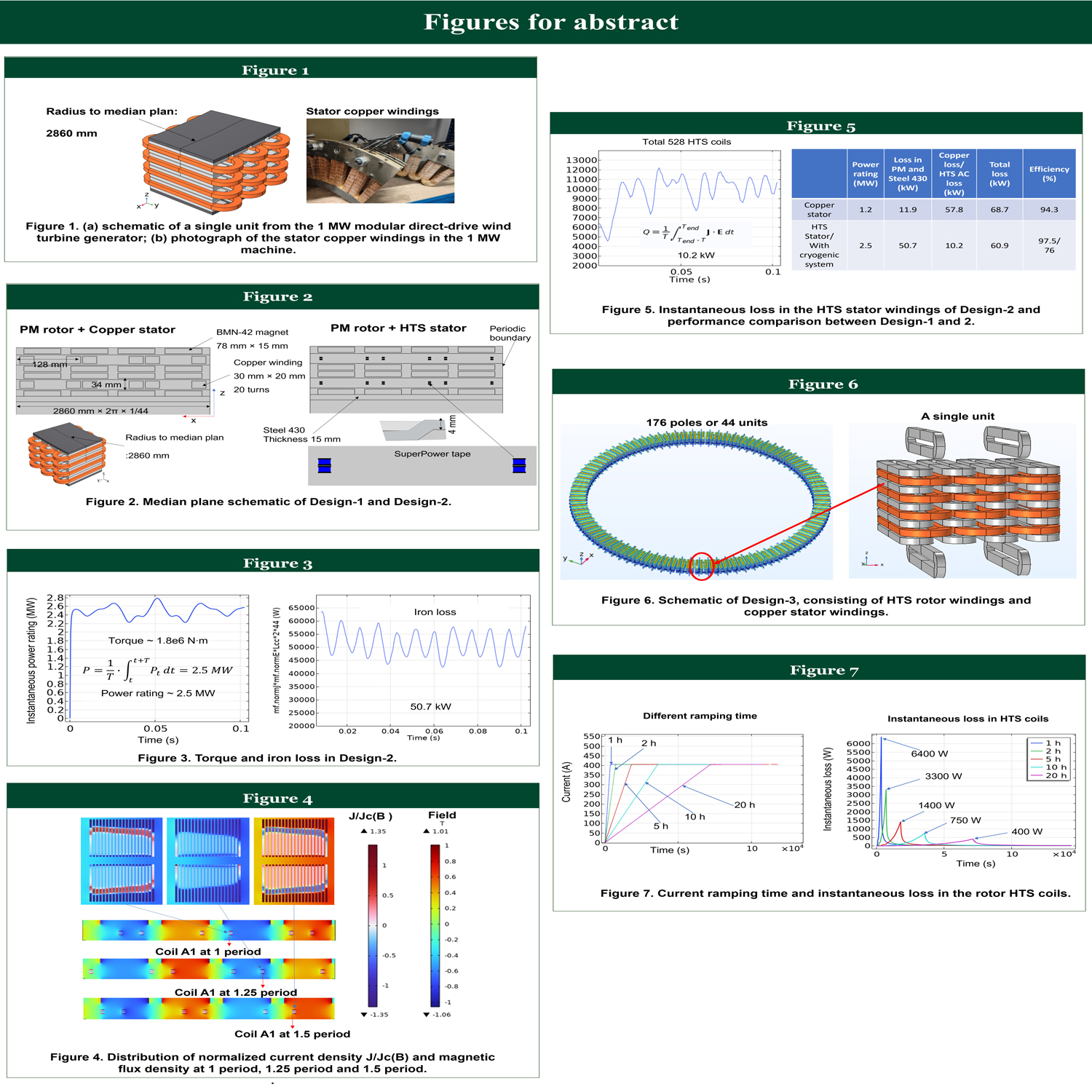
Figure 1(a) shows the schematic of a single unit from a 1 MW modular direct-drive wind turbine generator, while Figure 1(b) shows a photograph of the stator copper windings of this machine. The parameters of this 1 MW machine were applied in Design-1. As shown in Figure 2, Design-2 has a similar structure to Design-1 but replaces the copper windings in the stator with HTS windings. To simplify the FEM models, only 2D simulations in the median plane of each design were considered.
Figure 3 illustrates the estimated torque and iron loss in Design-2. Compared to Design-1, Design-2 shows an increase in power rating from 1.2 MW to 2.5 MW, while the iron loss rises from 12 kW to 50 kW. Figure 4 displays the distribution of normalized current density J/Jc(B) and magnetic flux density at 1, 1.25 and 1.5 periods. To reduce computation time of the FEM model, the moving mesh was constructed for the stator rather than the rotor. The instantaneous loss in the HTS stator windings, along with a performance comparison between Design-1 and Design-2, is presented in Figure 5.
In Design-3 and Design-4, the rotor magnets were substituted with HTS coils to increase the magnetic flux density in the air gap. Figure 6 illustrates the structure of the HTS rotor windings, designed to operate at a current of 405 A. To investigate the influence of ramping time on AC loss, we varied the operating current ramp-up duration to 1, 2, 5, 10, and 20 hours. The instantaneous loss in the rotor HTS coils is shown in Figure 7.
Overall, the simulation results suggest that replacing either the rotor permanent magnets or the stator copper windings with HTS coils can effectively increase the power rating of the generator. However, the cryogenic requirements will have an impact on the power density and overall system efficiency, which will be quantified as part of future work. For HTS rotor windings, extending the ramping time reduces peak AC loss, thereby reducing the cryogenic demands.
This work has been funded as part of a Royal Academy of Engineering Chair in Emerging Technologies project awarded to Prof. Mueller.
Additional information: figures are attached in the “More information” part of abstract submission.
AP2-6
Design methods for AC loss reduction in HTS linear motors for high-dynamic motion applications
17:15-17:30 Dec.3
*Arvind Desikan1, Dave C. J. Krop2, Bart de Bruyn2, Elena A. Lomonova2
Technische Universiteit Eindhoven1
Eindhoven University of Technology2
For the next generation of high-performance actuators in the manufacturing industry, High-Temperature Superconductors (HTS) are in consideration to replace the state-of-the-art permanent magnet linear motors. In general, linear motion systems in the manufacturing industry require motion profiles with high acceleration and short repetition times. A consequence is the highly dynamic armature field inducing significant magnetization losses in superconductors and eddy-current losses in the conductive media of a cryostat (cryostat wall, radiation shield and cooling platform). These losses impose significant challenges on the magnitude of cooling power as well as on the thermal stability of superconducting magnets for continuous dynamic performance. Through this work, numerous methods are investigated to reduce AC loss in the cryogenic assembly. These include a choice between a conduction-cooled and bath-cooled solution, affecting eddy-current losses, force density and magnetization loss in superconductors; designs of a cooling platform with slit-patterns to minimize eddy-current losses while not adversely affecting thermal conductance; superconducting coil wound with partially striated turns to reduce loss density at hotspots in a coil; and incorporating flux diverters and magnetic shields for loss reduction. To compare these methods, combinations of semi-analytical modeling and Finite-Element-Analysis (FEA) with an electro-thermal framework is applied to a linear motor composed of DC operated HTS coils in a stator and three-phase AC coils in the mover.
