Industrial and electric power applications
AP1-1-INV
The SuperLink Cable Project - Development and Impacts of a Superconducting Power Cable in a 110kV Distribution Network
9:45-10:15 Dec.3
*Wescley T. B. de Sousa1, Mathias Noe1, F. Boehm1, S. Grohmann1, W. Prusseit2, R. Bach3, P. Mansheim3, A. Alekseev4, D. Willén5, P. Michalek6 and R. Prinz6
Karlsruhe Institute of Technology, Hermann-von-Helmholtz-Platz 1, Eggenstein, 76344, Germany1
THEVA Dünnschichttechnik GmbH, Rote-Kreuz-Str. 8, Ismaning, 85737, Germany2
FH Südwestfalen, Lübecker Ring 2, Soest, 59494, Germany3
Linde GmbH, Dr. Carl-von-Linde-Str. 6-14, Pullach, 82049, Germany4
NKT GmbH & Co. KG, Düsseldorfer Str. 400, Köln, 51061, Germany5
Stadtwerke München, Emmy-Noether-Str. 2, 80992, Munich, Germany6
A major challenge nowadays of the 110 kV network in Munich is the off-peak times within the city, when the power generated at the southern substation should not only be available for Munich, but in an additional function exported to external networks. The existing lines are not enough to transport the produced energy from south to the northern and southern substations. To improve the situation, improve the security of supply and create efficient connections, a 12 km long Superconducting power cable connecting the load center in the south to the northern main substation is envisioned. Before integrating such cable in the network, however, a deep investigation of its effects in the network must be carried out. Therefore, load flow calculations were performed considering the network operation under different load and feeding scenarios. In order to evaluate the results, the loading of the lines, as well as voltage stability and short circuit current levels were analyzed. It was found that the SuperLink cable contributes not only to the relief of overloaded cables but also to the overall decrease of the losses in the network.
Figure 1. SuperLink Cable Design
Keywords: HTS Power Cable, Network Load Flow Calculation
AP1-2-INV
Development status of DC induction heating device for aluminum billets using high temperature superconducting magnet
10:15-10:45 Dec.3
*Satoshi Fukui
Faculty of Engineering, Niigata University, Ikarashi Ni-no-sho 8050, Niigata, 950-2181 Japan
The induction heating by rotating the aluminum billet in a strong DC magnetic field (DC induction heating) has been demonstrated to show high efficiency [1]. By applying HTS magnets for the DC induction heating, it is possible to significantly improve the heating capacity and the energy efficiency compared to the conventional high frequency induction heating. Research and development of DC induction heating using high temperature superconducting (HTS) magnets has been actively conducted in Europe since the early 2000s and a commercial model was developed around 2008. Subsequently, R&D was also started in Korea and China.
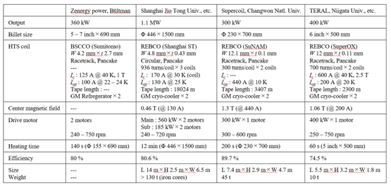
In 2008, Zenergy Power in collaboration with Bültman GmBH has developed a commercial DC induction heating device using HTS magnets [2]. The HTS magnet of this device made of BSCCO tape with 700 mm × 400 mm room temperature bore is placed on the center leg of E-shaped iron core with two separated air gaps. The two aluminum billets can be processed in parallel. The billet size range is 152 - 177 mm in diameter and 690 mm in length. The output power is 360 kW at the rotational speed of 240 - 750 rpm. This devoce was installed in Weseralu's aluminum plant in 2008 and 350,000 billets (about 10,000 tons, 2.2 ton/hr) were heat-treated in the three years from 2008 to 2010.
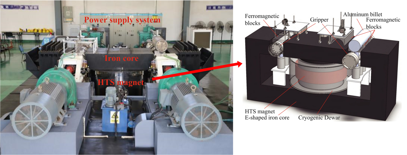
The Chinese research group (Shanghai Jio Tong University and others) has developed a 1 MW-class heating device for billets of 460 - 640 mm in diameter [3]. The HTS coil wound with SST (Shanghai Superconductor) REBCO tape wire coupled with the iron core. The iron core has two air gaps as same as that of Zenergy’s device. The magnetic field applied to the billets in two air gaps is about 0.45 T. The total wire length exceeds 18 km and the inductance in combination with the iron core is 189 H. In this device, two motors with different outputs are used. In the rapid heating from room temperature, the main motor is used to input large power. After rapid heating, it is switched to the auxiliary motor with the smaller output and the heat input is controlled to equalize the temperature distribution. The proper use of the large and small motor contributes to improve overall efficiency. The overall dimensions of the machine are 14 m/6.5 m/2.5 m and the weight of the iron core is 130 tons.
Supercoil Co. Ltd. and Changwon National University have developed a 300 kW-class DC induction heating system using high-temperature superconducting coils for aluminum billets [4]. In this device, two HTS coils wound by the SuNAM REBCO tape wire are used. Each HTS coil is separately enclosed in the cryostat with the room temperature bore. These two HTS coils are placed against each other combined with a C-shape iron core. The iron core through the HTS coil is partly movable in the gap direction corresponding to the billet diameter. The operating temperature and rated current of the HTS coils are 10 K 650 A respectively. The inductance is 1.6 H when combined with the iron core and the magnetic field at the center of the air gap is up to 1.5 T. The processable billet size is within 240 mm in diameter and 700 mm in length.
In Japan, a demonstration device of DC induction heating of aluminum billets using HTS magnet has been developed by the group of Terral Inc., Niigata University, Chubu Electric Power Company and AIST [5]. The heating capacity of this demonstration device is 400 kW to heat 40 aluminum billets of nominal diameter 6 inches (about 155 mm) and length 500 mm from 20°C to 500°C per hour. The HTS magnet consists of a pair of racetrack coils wound by REBCO tape of Super-OX (now Faraday Factory Japan). The HTS coil is wound directly around the iron core. This part is located in the cryostat and cooled to cryogenic temperature. The backs of the two sets of HTS coils are connected by a yoke placed at room temperature. This structure can effectively save the necessary amount of HTS tapes in the coils. At the operating temperature of 20 K, the HTS magnet can apply the magnetic field of 1 T to the aluminum billet at the rated current of 200 A. The heating power of 400 kW can be input to the billet at 750 rpm. It was demonstrated that the aluminum billet with the nominal diameter of 6 inches and a length of 500 mm can be heated from room temperature to 500°C within 60 seconds and the heating efficiency was 74.5%. It was also demonstrated that through the continuous heating operation of 90 billets/2 hours, the soundness of the HTS magnets was not compromised.
Table 1 summarizes the specifications of these developed DC induction heating device using HTS magnet.
[1] M. Fabbri, A. Morandi and P. L. Ribani, "DC induction heating of aluminumbillets using superconducting magnets", COMPEL, vol. 27, no. 2, pp. 480-490, 2008.
[2] M. Runde, N. Magnusson, C. Fülbier and C. Bührer, “Commercial Induction Heaters With High-Temperature Superconductor Coils”, IEEE Trans. Appl. Supercond. 21, pp.1379-1383, 2011.
[3] S. Dai, X. Yan, Z. Hong, T. Ma, R. Wu, Z. Li, Z. Zeng. P. Yang, L. Hu, T. Zhang and B. Wang, “Development and Test of One Commercial Megawatt Superconducting DC Induction Heater With Extra High Energy Efficiency”, IEEE Access 9, pp.3301-3314, 2021.
[4] J. Choi, T. Kim, C. K. Lee, D. S. Jeon, G. W. Park, S. Cho, M. Park, I. K. Yu and M. Iwakuma, “Commercial Design and Operating Characteristics of a 300 kW Superconducting Induction Heater (SIH) Based on HTS Magnets, IEEE Trans. Appl. Supercond. 29, Art no. 3700105, 2019.
[5] T. Ito, S. Fukui, H. Kawashima, Y. Ogata, T. Sho, M. Furuse, T. Watanabe, S. Nagaya, J. Ogawa, Y. Morishita, N. Fuyama, T. Nagaoka, N. Nawachi, “Development of 400 kW Class Aluminum Billet Heater using HTS Magnet”, IEEE Trans. Appl. Supercond., 33, Art no. 4600505, 2023.
Table 1 Comparison of specifications developed DC induction heating device using HTS magnet.
Keywords: DC induction heating, billet heater
AP1-3-INV
Force-Balanced Coils for HTS-SMES
10:45-11:15 Dec.3
*Shinichi Nomura
School of Science and Technology, Meiji University, 1-1-1 Higashimita Tama-ku, Kawasaki, Kanagawa, 214-8571 & Japan
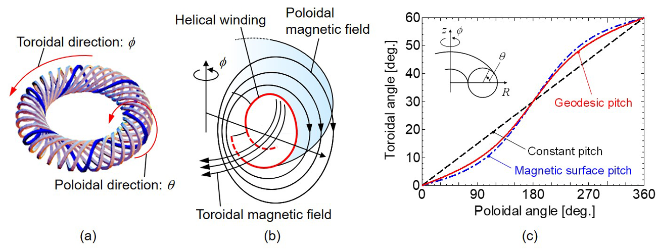
Force-balanced coils (FBCs) can balance the electromagnetic forces through a helically wound configuration and minimize the required mass of structures for energy storage based on the virial theorem [1]. Figure 1(a) shows a schematic illustration of the FBC windings. The darker hatch indicates one complete helical winding. The FBCs in Fig. 1(a) consist of six helical coils with six poloidal turns per toroidal turn.
High-temperature superconductors are expected to reduce refrigerator energy consumption for superconducting coils. The author conducted a design study of a 360-MWh SMES for daily load leveling using 15-kA REBCO conductors [2]. The 360-MWh SMES consists of 4000 superconducting coils with the FBC configuration. The energy cycle efficiency is estimated at least 70% with a cooling temperature of 20 K.
The FBCs can also reduce the vertical magnetic field that penetrates the helical windings by modulating the pitch of the winding. Figure 1(b) shows a schematic illustration of an ideal magnetic field distribution of the FBCs. One poloidal magnetic surface matches up with the coil surface to reduce the vertical magnetic field. By the effect of the modulated winding pitch, the FBCs can be expected to reduce the degradation of the critical current caused by the vertical magnetic field that penetrates REBCO conductors. However, three-dimensional complex shapes of the FBC helical windings may lower the critical current of REBCO conductors. In particular, the in-plane curvature of the FBC applies the edgewise strains to REBCO conductors. A geodesic trajectory of the FBC windings becomes one of the feasible solutions to minimize the in-plane curvature variations of the helical windings, effectively leading to minimizing the edgewise strains in REBCO conductors. The pitch modulation of the helical windings can also achieve the geodesic trajectory. To establish the winding technique of helical coils without a decrease in the critical current of REBCO conductors, the author’s research group develops a prototype of a winding machine for the FBC and designs a 1-T class small model coil using REBCO conductors [3].
This work discusses the design considerations of the FBC windings for SMES using high-temperature superconductors. First, the author summarizes the design conditions of the FBC windings and introduces the progress of the FBC research. Second, the author investigates the magnetic field distribution of the FBC windings and evaluates the feasibility of preventing the critical current degradation of high-temperature superconductors due to the vertical magnetic field. Figure 1(c) compares the pitch modulations between the magnetic surface pitch (minimization of the vertical magnetic field) and the geodesic pitch. Although the geodesic pitch will have almost the same trajectory as the magnetic surface pitch, a detailed evaluation of the vertical magnetic field is required. Finally, based on the scaling law, the author estimates the theoretical energy cycle efficiency determined by the mass of structures, the ampere-meters of high-temperature superconductors, and heat loads and explores the potentiality of the FBCs as SMES coils using high-temperature superconductors.
[1] S. Nomura and H. Tsutsui, “Structural limitations of energy storage systems based on the virial theorem,” IEEE Trans. Appl. Supercond., vol. 27, no. 4, Jun. 2017, Art. No. 5700106.
[2] S. Nomura, H. Chikaraishi, H. Tsutsui, and R. Shimada, “Feasibility study on large scale SMES for daily load levelling using force-balanced helical coils,” IEEE Trans. Appl. Supercond., vol. 23, no. 3, Jun. 2013, Art. No. 5700904.
[3] H. Kamada, A. Ninomiya, S. Nomura, T. Yagai, T. Nakamura, and H. Chikaraishi, “Development of 1-T class force-balanced helical coils using REBCO tapes,” IEEE Trans. Appl. Supercond., vol. 30, no. 4, Jun. 2020, Art. No. 4600905.
Figure 1. Schematic illustration of the FBC windings (a), the magnetic field distribution (b), and an example of the FBC winding trajectories depending on the difference of the pitch modulations (c).
Keywords: Electromagnetic force, helical coil, high-temperature superconductor, SMES
AP1-4-INV
AC Loss Characteristics of an HTS Coil with Ferrite Cores for a Wireless Power Transmission System
11:15-11:45 Dec.3
*Ryota Inoue1, Takahiro Iwamoto1, Haruki Komoda1, Hiroshi Ueda1, and SeokBeom Kim1
Graduate School of Environment, Life, Natural Science and Technology, Okayama University, 3-1-1 Tsushima-naka, Kita-ku, Okayama 700-8530, Japan1
The demand for electric vehicles (EVs) has been increasing due to the global warming issue. On the other hand, a major issue for EVs is the excessively long charging time. Therefore, it is necessary to develop a wired power transmission system of 100 kW class for EVs. However, such systems have inherent issues, including the risks of electric shock, discharge, and wear on the charging connectors. Therefore, there is a growing need for large-capacity wireless power transmission (WPT) systems capable of transmitting several 100 kW. On the other hand, to achieve 100 kW-class WPT systems for EVs, it is necessary to lower the operating frequency to below 10 kHz. This is crucial for reducing both the switching losses in the power converter and the eddy current losses in the coils [1]. However, conventional large-capacity and low-frequency WPT systems using copper coils have the problem of temperature rise due to heat generation within the coils. Thus, we have been investigated a several 100 kW-class WPT system for EVs in which a high-temperature superconducting (HTS) coil is installed only on the ground side [2]-[3]. In order to realize the high energy density WPT system using HTS and copper coils for EVs, it is important to install ferrite cores on the back of the coils. Particularly for the ground-side HTS coil, ferrite cores may also need to be cooled. On the other hand, the magnetic properties of ferrite cores in the kilohertz frequency band at temperatures of liquid nitrogen and the AC loss characteristics of the HTS coil with ferrite cores for the WPT system have not been satisfactorily clarified.
In this presentation, we focused on a toroidal sample of ferrite cores commonly used as back yokes in WPT systems and evaluated its magnetic properties in the kilohertz frequency band at liquid nitrogen temperatures. We also measured the AC loss of the HTS coil under three different conditions: without ferrite cores, with ferrite cores placed inside the cryostat (ferrite cores and HTS coil at liquid nitrogen temperature), and with ferrite cores placed outside the cryostat (ferrite cores at room temperature and HTS coil at liquid nitrogen temperature). The measured results of these experiments will be presented.
[1] K. Ukita, T. Kashiwagi, Y. Sakamoto, and T. Sasakawa, “Evaluation of a non-contact power supply system with a figure-of-eight coil for railway vehicles,”Proc. IEEE PELS Workshop Emerging Technol.: Wireless Power, pp. 1-6, 2015.
[2] Y. Inoue, R. Inoue, H. Ueda, and S. B. Kim, “Basic Study of a Wireless Power Transmission System Using Superconducting Coil as a Ground-Side Coil for Electric Vehicles,” IEEE Trans. Appl. Supercond., vol. 33, no. 5, pp. 1-4, 2023, 5400605.
[3] R. Inoue, T. Iwamoto, H. Komoda, H. Ueda, and S. B. Kim, “Basic Experimental Study on a 1 kW-Class WPT System Using HTS and Copper Coils for EVs,” IEEE Trans. Appl. Supercond., vol. 34, no. 3, pp. 1-4, 2024, 5901305.
Keywords: AC loss, HTS coil, ferrite, wireless power transmission
AP1-5
Development and implement of MW High Temperature Superconducting Induction Heater
11:45-12:00 Dec.3
*Dai Shaotao1, Ma Tao1, Jiang Guozhong2, Hu Lei1, Yang Junfeng1
School of Electrical Engineering, Beijing Jiaotong University, Beijing1
Jiangxi Liannovation Superconductor Co., Ltd., Nanchang2
Energy conservation and emission reduction is a critical task for China’s aluminum industry. Different from the present AC induction heater, HTS direct current (DC) induction heater is expected to significantly improve the energy efficiency of preheating aluminium billets before extrusion process. The world’s first commercial megawatt HTS DC inducting heater based on 2nd generation HTS tapes has been developed and put into operation. In this paper, the commercial design of this 1 MW HTS DC induction heater including design specifications, energy efficiency and commercial potential are presented and analyzed thoroughly. Subsequently, the manufacture and operation of three core parts including HTS magnet with extra-large diameter, iron core structure and electrical driving system, are introduced. The excitation current of 130 A to the magnets coupled with iron core can generate a magnetic flux density larger than 0.45 T at the center of the air gaps. Test results showed that the HTS DC induction heater has much higher energy efficiency (80 - 90%) than its AC counterpart (40 - 50%). Over years of operation and testing on this machine have validated the practicability and reliability of megawatt HTS DC induction heater concept.
Fig.1 Structure of the HTS DC induction heater.
Keywords: Induction heater, Superconducting magnet, YBCO


