Numerical simulation and AC loss
AP3-1-INV
Numerical modeling of superconductors: state of the art, current challenges and future trends
17:45-18:15 Dec.3
*Francesco Grilli
Institute for Technical Physics, Karlsruhe Institute of Technology, Herman-von-Helmholtz Platz 1, 76344 Eggenstein-Leopolshafen, Germany
Numerical modeling is an effective tool for predicting the behavior and optimizing the performance of superconducting applications. When it comes to high-temperature superconductors (HTS), a particular aspect of interest is the understanding of their electromagnetic behavior, which requires to know the distribution and temporal evolution of electric current and magnetic fields. In the past three decades, and particularly in the last two, different numerical models have been developed, based on different mathematical methods. In this contribution, the current state of the art of this field is described. Particular attention is given to HTS coated conductors, for which the challenge of simulating a superconducting layer with high width-to-thickness ratio contributed to the development of new models that are both accurate and fast. The current limits of the field of numerical modeling of superconductors, the upcoming challenges and the foreseeable trends are also discussed, always with a look at realistic applications.
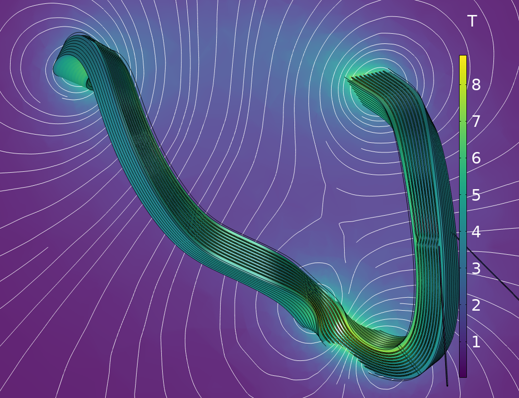
Figure 1. Magnetostatic simulation of a non-planar HTS coil for a compact fusion reactor. Figure courtesy of N. Riva (Proxima Fusion).
Keywords: Numerical modeling, HTS applications, numerical methods.
AP3-2
Numerical simulation for AC loss estimation of multi-bundled no-insulation REBCO coils under fluctuating external fields
18:15-18:30 Dec.3
*Takanobu Mato1, So Noguchi1
Hokkaido University, Kita 14 Nishi 9, Sapporo, Hokkaido, 060-0814 Japan1
The rare-earth barium copper oxide (REBCO) conductors ideally have an excellent performance for compact electrical machines primarily due to their high current capacity and high mechanical tolerance. Recently, the toroidal field magnet development for nuclear fusion reactors by Commonwealth Fusion Systems (CFS) and Massachusetts Institute of Technology (MIT) has been attracting attention [1]. The successful development of the large-sized REBCO magnets is attributed to the no-insulation (NI) and the multi-bundle (MB) technologies. The NI technology eliminates the insulation between turns, resulting in the high thermal stability. Meanwhile, the MB technology, where multiple bundled REBCO tapes are wound into a coil shape, enables mitigation of the charging delay issue arising from the NI technique.
The majority of MB NI REBCO coils including the toroidal field coils is designed for DC operations. Nevertheless, even in these DC applications, the REBCO coils experience external field fluctuations, transient electromagnetic variation, and any kind of AC ripples. These field fluctuations cause magnetization losses, and it deteriorates the stability of MB NI REBCO coils. The MB NI REBCO coil has a well-balanced performance in thermal stability and charging speed; however, the current behaviors are complicated, and the AC losses are generated. This is due to the intricate current paths inside the coil, which depend on the tape-to-tape and the turn-to-turn contact resistances. The complicated current behaviors and the AC losses must be clarified to fully exploit the coil performances.
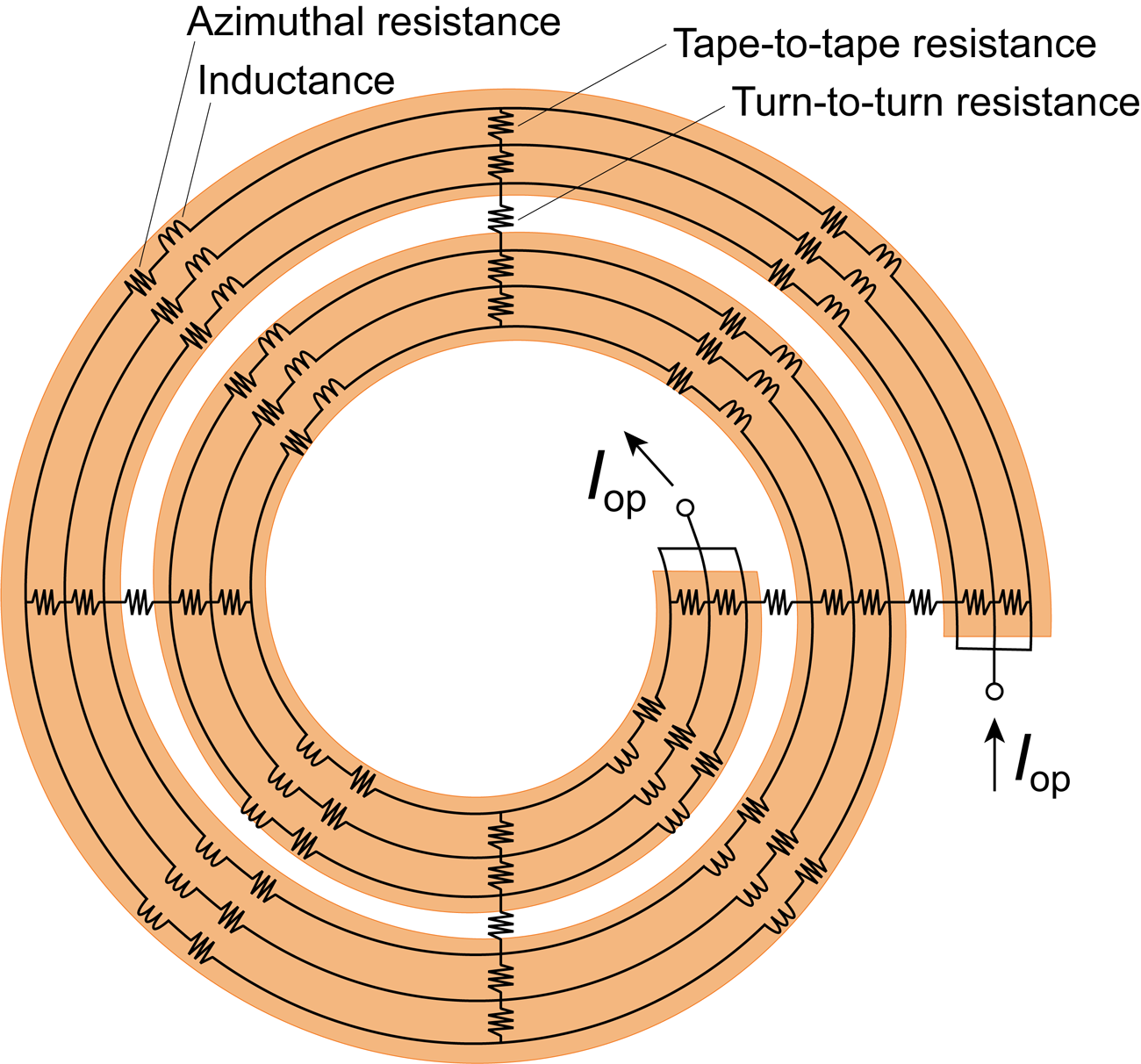
In the presentation, the developed simulation tool for the AC loss estimation of the MB NI REBCO coil will be shown, and the AC loss behaviors will be investigated numerically. Fig. 1 shows the developed partial element equivalent circuit (PEEC) model of the MB NI REBCO coil. It is noted the coil shown in Fig. 1 has 2 turns wound with 3 bundled tapes. The bare REBCO tapes have the inductances and the tape-longitudinal resistances. The turn-to-turn and the tape-to-tape contact resistances are distinguished and modeled separately. The “intra-turn” and “inter-turn” Joule heat losses are estimated from the PEEC simulation results. The hysteresis loss is also derived based on Bean’s model, and the calculated losses will be shown.
[1] Z. S. Hartwig et al., “The SPARC Toroidal Field Model Coil Program,” IEEE Trans. Appl. Supercond., vol. 34, no. 2, 2024, Art. no. 0600316.
Figure 1. Partial element equivalent circuit (PEEC) model of MB NI REBCO coil. The figure shows an example of the MB NI REBCO: 3-tape-bundled 2-turn MB NI coil.
Keywords: AC loss, multi-bundled REBCO coil, no-insulation winding
AP3-3
Contact resistance between REBCO coated conductors applied with the metal-insulator material (Pr0.8Sm0.2)0.6Ca0.4CoO3
18:30-18:45 Dec.3
*Kyosuke Sakurai1, Yuji Tsuchiya1, Masahiro Tahashi2, Hideo GOTO2, Tatsunori Okada1, Satoshi Awaji1
Tohoku University1
Gakko Hojin Chubu Daigaku2
Since REBa2Cu3O7-δ. (REBCO) coated conductors (CCs) have the advantage of a high critical current density in high magnetic fields, they are expected to be applied to high field magnets, however they often burn out due to thermal runaway if there is a local defect. Although the "no insulation coil" was developed to protect the REBCO coil against thermal runaway, it has the disadvantage of low magnetic field stability due to current transfer between neighboring tapes in the windings [1]. Recently, “smart insulation (SI) coil” has been proposed to achieve both stability in insulated coils and protection in NI coils through using the metal-insulator transition (MIT) materials, which changes the coil from an insulated to no insulation coil only when thermal runaway occurs [2]. As a candidate of MIT materials, we focus on Co-based perovskite oxide (Pr0.8Sm0.2)0.6Ca0.4CoO3 (PSCCO), which is fabricated using the sol-gel method [3]. In this study, we fabricated polycrystalline bulks of PSCCO and measured their resistivity ρ and MIT temperature TMI at low temperatures. Furthermore, we prepared the PSCCO slurry, and applied it to REBCO CCs and measured the contact resistance Rs between them.
Polycrystalline PSCCO were fabricated by the sol-gel method [3]. Firstly, gels were synthesized from an ethanol suspension (sol) of metal acetates by a ultrasound irradiation. The gels were dried and then sintered at 800 °C in air for 12 hours. Next, pellets formed from the ground powder were annealed at 1200 °C in oxygen gas flow. The pellets were cut into rectangular shape by a diamond saw for a resistivity measurement. On the other hand, the PSCCO slurry was fabricated using N-Methyl-2-Pyrrolidone (NMP) as a solvent and polyvinylidene fluoride (PVDF) as a binder. To begin with, the PSCCO sample was ground into the powder using an alumina mortar and pestle for one hour. Secondly, NMP and PVDF were added to a sample vial and heated on a hot plate at 100 °C for 40 minutes to dissolve the PVDF. Then, the PSCCO slurry was prepared by adding the PSCCO powder to the sample vial and mixing it with an automatic mixer for one minute. Finally, the slurry was painted onto the REBCO tapes using a toothpick and dried them on a hot plate at 100 °C for one hour. The temperature dependence of ρ in the polycrystalline samples and Rs in the contact between the CCs were measured from 10 to 270 K using the DC four-probe method. The T MIT was determined as the temperature at which the temperature derivative of ρ and Rs were maximum.
According to the transport measurement, the ρ in PSCCO bulk was decreased sharply at TMIT= 74 K with increasing temperature. The ρ of PSCCO changed by more than three orders of magnitude from 3360 mΩcm at 270 K to 4.6 mΩcm at 10 K. On the other hand, Rs between REBCO tapes was gradually decreased by over four orders of magnitude due to the MIT of PSCCO from 10 K to 270 K. The Rs was 1.6 × 10⁶ mΩcm² at 10 K and 7.5 × 101 mΩcm² at 270 K, respectively. The TMIT obtained from the Rs measurement was 76 K. It was found that the change in ρ and Rs differed by one order of magnitude. This difference is considered to be due to the interfacial resistance between the REBCO CCs and the dried PSCCO slurry.
We will discuss the Rsin the PSCCO-coated REBCO tapes in comparison with the earlier reports about other MIT materials such V₂O₃ [4].
[1] S. Hahn et al., IEEE Trans. Appl. Supercond. 21, 1592 (2011).
[2] H.-W. Kim et al., IEEE Trans. Appl. Supercond. 27, 461704 (2017).
[3] M. Tahashi et al., Jpn. J. Appl. Phys. 61, 018003 (2022).
[4] M. Bonura et al., IEEE Trans. Appl. Supercond. 33 8800106 (2023).
This work was supported by Grant-in-Aid for JSPS Fellows Grant Number JP24KJ0385.
Keywords: Quench protection, Smart insulation, Metal-insulator transition (MIT), Contact resistance
AP3-4
AC loss reduction in a REBCO coil assembly by applying superconducting shielding coils and magnetic flux diverters
18:45-19:00 Dec.3
*Yueming Sun1, Shuangrong You2, Taotao Huang3, Zhenan Jiang1
Victoria University of Wellington1
The University of Edinburgh2
HTS-1103
A 10 T fast-ramping high-temperature superconducting (HTS) magnet will be designed to characterize new rare-earth permanent magnet materials. However, AC loss associated with the fast-ramping process is one of the critical issues. The primary goal of the 10 T magnet project is to find an effective way to reduce AC loss. One method is applying magnetic flux diverters (MFDs) to HTS magnets. However, the benefits of MFDs diminish in high magnetic fields that exceed the saturation field of the MFDs. To address this challenge, superconducting shielding coils (SSCs) can be an alternative solution due to their high-field diamagnetic properties.
In an initial step of this project, AC loss in a small-scale superconducting magnet was numerically studied using SSCs, MFDs, and a combination of SSCs and MFDs. The magnet consists of four double pancake coils (160 turns in total) and was wounded from 4 mm wide REBCO wire. The self-field critical current of the coil assembly is 51 A at 77 K. The simulated results show that SSCs can effectively reduce AC loss by 50% at a coil current of 50 A. This reduction can be further increased to 90% when combining SSCs and MFDs, providing an even more efficient solution.
This work was supported in “Fast-ramping superconducting magnets” funded by US Office of Naval Research under Grant award No. N629092412037.
AP3-5
Magnetisation loss behaviour in insulated and non-insulated HTS REBCO double-pancake and racetrack coils of the same dimensions at 77 K
19:00-19:15 Dec.3
*Ben George Koshy1, Konstantinos Bouloukakis1, Mark Ainslie2, Yueming Sun1, Rodney A. Badcock1, Ben Mallett1, Zhenan Jiang1
Paihau-Robinson Research Institute, Victoria University of Wellington, Wellington 6140, New Zealand1
King’s College London, London WC2R 2LS, U.K.2
In many high-temperature superconducting (HTS) applications, such as high-field magnets, rotating machines, and linear actuators, no-insulation (NI) coils are an appealing alternative to insulated (INS) coils. The advantages of NI coils, including higher current density, better mechanical integrity, thermal stability, and self-protecting properties, make them a more attractive technological choice compared to INS coils [1]. In the applications mentioned, coils are exposed to time-varying magnetic fields that induce magnetization loss. The loss characteristics may differ between NI and INS coils, and this must be addressed before replacing INS coils. This loss can vary depending on the applied field angle and frequency, creating a parasitic heat load that significantly impacts the design of cryogenic systems. Therefore, it is essential to investigate the behavior of this loss under different conditions to ensure successful system design.
In this work, we investigate magnetization loss in NI and INS double-pancake and double-racetrack coils both experimentally and numerically. Experiments were conducted at 77 K under AC external magnetic fields up to 100 mT, considering various field angles (0o ̶ 90o) and frequencies (72-146 Hz) in NI and INS coils of the same dimensions, wound with SuperPower superconductors. Numerical results from a 3D model of the NI and INS coils, implemented in COMSOL Multiphysics, are then compared with the measured loss values. Additionally, we analyze current density distributions and magnetic field penetration profiles to better understand the magnetization loss behaviors in NI and INS coils.
[1] S. Hahn, K. Radcliff, K. Kim, S. Kim, X. Hu, K. Kim, D. V. Abraimov and J. Jaroszynski, “Defect-irrelevant behavior of a no-insulation pancake coil wound with REBCO tapes containing multiple defects,” Supercond. Sci. Technol., vol. 29, Art. no. 105017, September 2016.
This work was in part supported by the New Zealand Ministry of Business, Innovation and Employment under the Advanced Energy Technology Platform program “High power electric motors for large scale transport” contract number RTVU2004 and in part supported by the Air Force Office of Scientific Research under award number FA2386-22-1-4054.

