AP7-6
Long-range measurement experiment with all-optical cryogenic liquid level sensor
14:30-14:45 Dec.5
*Toshiyuki Oikawa1, Kodai Yasuda1, Muneo FUTAMURA1, Shigeo Miura1, Hiroshi Okamoto1
Akita Prefectural University1
1. Introduction
Liquid hydrogen could potentially be used as a coolant for superconducting cables for electrical power transmission [1]. In addition, hydrogen is a candidate for energy storage in the current shift to renewable energy.
Liquid level gauges are needed to manage liquid hydrogen. Existing liquid level gauges for liquid hydrogen tend to have components and electrical wiring in contact with the liquid. This poses problems of liquid loss due to heat transfer and potential accident risk due to a surge current etc.
We are developing an all-optical, completely non-contact liquid level sensor for liquid hydrogen that does not use electrical wiring in the container. Previously [2], we performed an experiment using liquid nitrogen with the distance between the level sensor and the liquid surface being ≈ 30 cm. Here we report on an experiment, wherein the distance is increased to ≈ 1 m.
2. Principle of measurement
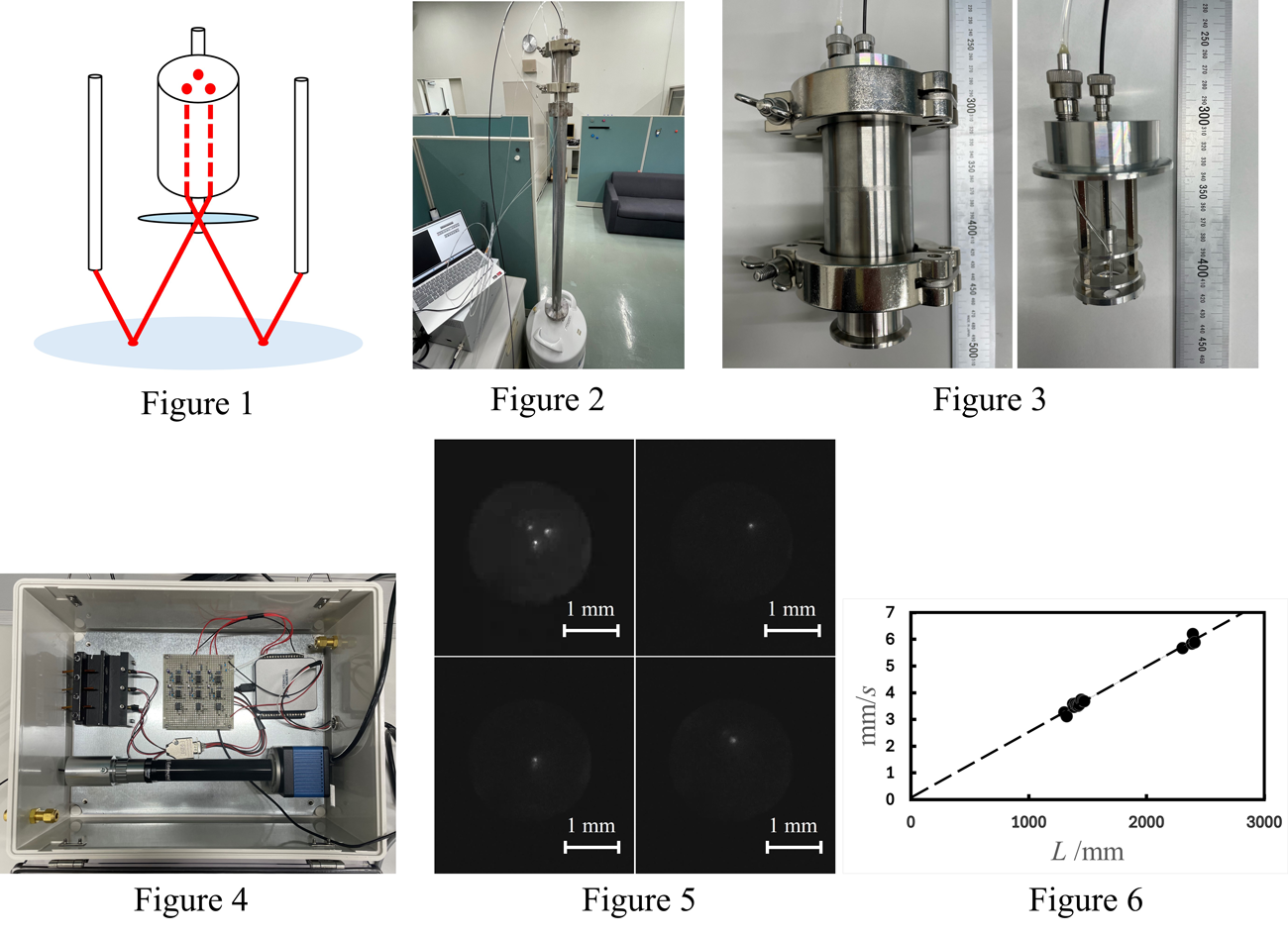
The measurement principle is shown in the Fig. 1. The liquid level sensor consists of three optical fibers, a fiber bundle, and a lens. When light is irradiated onto the liquid surface from the tips of the three optical fibers, the image reflected on the surface of cryogen is formed on the end surface of the fiber bundle through the lens. The reflected image is a triangle of three light points, and the size of the triangle is a function of the liquid level.
When the liquid surface is not still, the three light points also move around and they could overlap each other, making it difficult to observe the triangle. Therefore, the position of each light point and the size of the triangle can be obtained by observing the reflection image of each light point one at a time and averaging the multiple observation data.
3. Experiment
Figure 2 shows an overall view of the experimental equipment. We used liquid nitrogen for this study, and an experiment using liquid hydrogen is underway. The 1.0 m long tube for a long-range measurement was placed at the mouth of the liquid nitrogen tank, and the liquid level sensor was placed on top of the tube.
Figure 3 shows the liquid level sensor. The liquid level sensor consists of three optical fibers, a fiber bundle, a lens to focus the reflected image, and a lens to focus the light irradiated on the liquid surface. A KF50 flange and a KF50-KF40 reducer are connected to the liquid level sensor. This allows us to connect the sensor to a KF40 flange on a glass dewar for liquid hydrogen.
Figure 4 shows an experimental box. When conducting experiments using liquid hydrogen, electronic devices such as cameras need to be placed inside a box that is filled with nitrogen to prevent contact between the electronic devices and hydrogen. A camera (pco.panda) for observing reflected images, an irradiation coupler, an irradiation control circuit, and an interface (NI USB-6002) to a PC are placed inside the box. In observations of reflected images, the intensity of light is inversely proportional to the square of the distance, making it difficult to observe the reflected image when measuring over long distances. Therefore, a high-sensitivity camera that can observe the reflected image is used. The irradiation manifold consists of an optical fiber tip, a lens, and a semiconductor laser to provide a stable light beam to the optical fiber. The semiconductor lasers are connected to a PC through an irradiation control circuit and interface and are programmed to blink in sequence using a Python program.
4. Experimental results
Figure 5 shows an observed reflection image. The reflection image is part of a movie that was saved as a frame-by-frame image using movie editing software. Since the video is 60 FPS, the image acquisition rate is approximately every 0.017 s. The semiconductor lasers are repeatedly turned on for 0.1 s and then turned off for 0.1 s. Therefore, it is possible to save 5 to 6 images of the reflection of each light point out of the three light sources. The position of each light spot is determined from these observed images by image processing. First, we compute the difference between the image with the light spot and the image without the light spot. We then detect objects by removing signals below a threshold value, and then compute the center of gravity of the remaining signal. This operation is performed on multiple images, and the average of the center of gravity is obtained. The coordinates of this average are considered to be the center coordinates of the light point. In this way, the center coordinates of each of the three light points is obtained, and the distance between the light points is calculated.
Figure 6 plots the distance L between the liquid surface and the sensor against the distance between the light spots on the acquired images. In this experiment, two 1.0 m tubes were used, and measurements were made at distances of L = 1300 mm ~ 1500 mm and L = 2300 mm ~ 2500 mm.
An approximate straight line was obtained from the measurement results, and the RMS value of the horizontal misalignment was determined to be 52.6 mm. This value is considered to be the measurement accuracy.
5. Future Tasks
The center coordinates of the light point obtained this time are the coordinates obtained from the data observed when the liquid surface was stationary. We plan to extend our experiment to cases wherein the liquid surface is not still.
In addition, measurements using liquid hydrogen are underway.
