AP2-5
Numerical Study of a Direct Drive Generator for Wind Turbine with and without HTS Windings
17:00-17:15 Dec.3
*Shuangrong You, Hongye Zhang, MARKUS Mueller
The University of Edinburgh
High-temperature superconductors (HTS) show potential advantages in generator design by enabling higher power density and more compact generator size. However, incorporating HTS windings necessitates a cryogenic system, which can increase costs, add weight, and reduce overall generator efficiency. Therefore, investigating AC loss in HTS windings is crucial, as the loss largely determine the cryogenic requirements. In this work, we have numerically investigated AC loss in a MW-class modular wind turbine generator consisting of 176 rotor poles. Each 4-pole group serves as a modular unit to facilitate easy installation and removal. Finite-element method (FEM) modelling was applied using COMSOL Multiphysics to build generator models with and without HTS windings.
Four designs were analyzed in this study. Design-1 follows a conventional structure and serves as a reference, utilizing permanent magnets for the rotor and copper windings for the stator. Design-2 and 3 incorporate partial HTS structures. Design-2 replaces the stator copper coils with HTS windings, while Design-3 substitutes the rotor permanent magnets with HTS windings. Design-4 features a fully HTS design, with both HTS rotor and stator. Dynamic analysis of induced voltage in the armature windings and AC loss in the HTS windings was conducted using moving meshes. Simulation results indicate that both partial and fully HTS design offer higher power density compared to the conventional design. However, managing the heat generated by AC loss in HTS armature windings remains challenging, even at low rotating speeds in cryogenic environments.
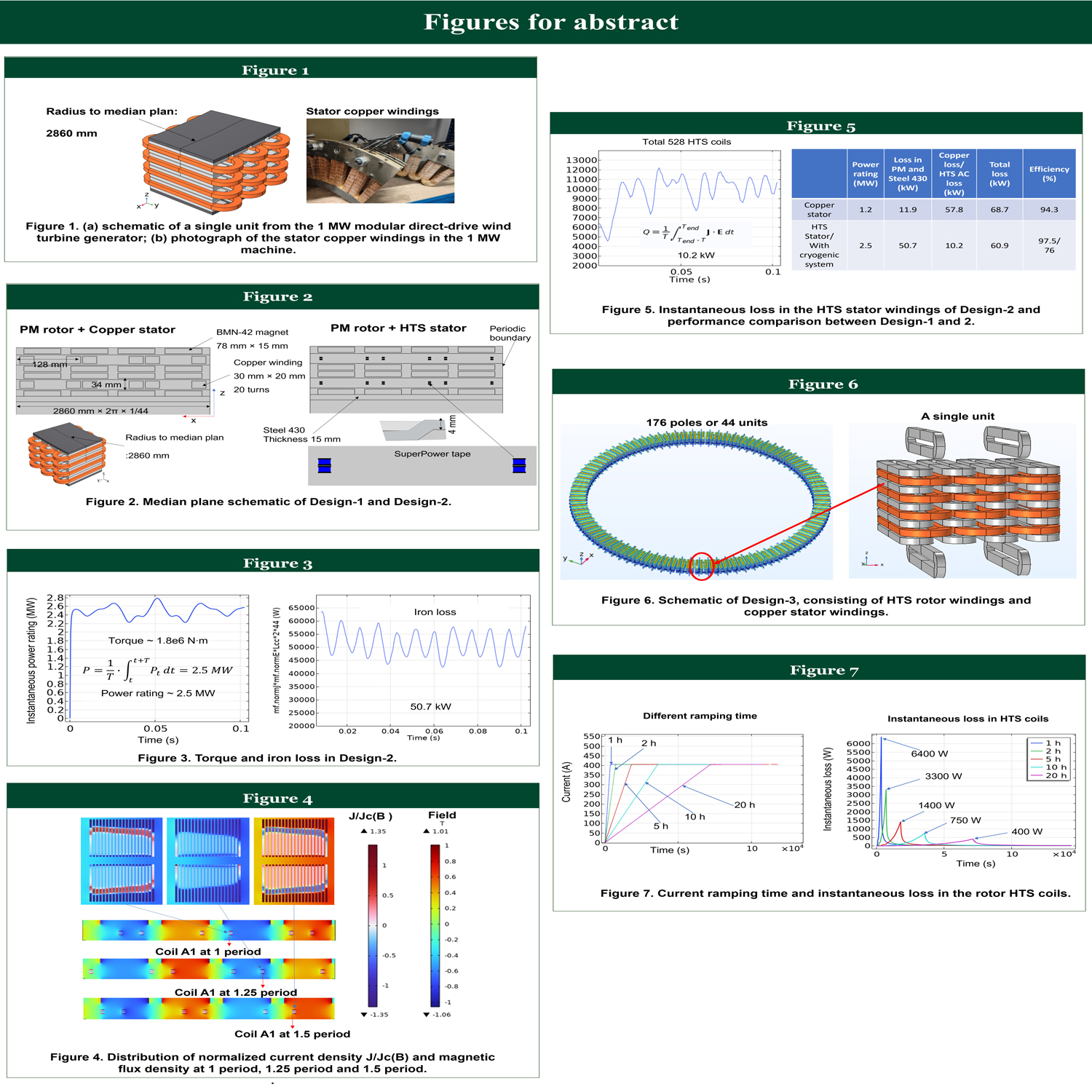
Figure 1(a) shows the schematic of a single unit from a 1 MW modular direct-drive wind turbine generator, while Figure 1(b) shows a photograph of the stator copper windings of this machine. The parameters of this 1 MW machine were applied in Design-1. As shown in Figure 2, Design-2 has a similar structure to Design-1 but replaces the copper windings in the stator with HTS windings. To simplify the FEM models, only 2D simulations in the median plane of each design were considered.
Figure 3 illustrates the estimated torque and iron loss in Design-2. Compared to Design-1, Design-2 shows an increase in power rating from 1.2 MW to 2.5 MW, while the iron loss rises from 12 kW to 50 kW. Figure 4 displays the distribution of normalized current density J/Jc(B) and magnetic flux density at 1, 1.25 and 1.5 periods. To reduce computation time of the FEM model, the moving mesh was constructed for the stator rather than the rotor. The instantaneous loss in the HTS stator windings, along with a performance comparison between Design-1 and Design-2, is presented in Figure 5.
In Design-3 and Design-4, the rotor magnets were substituted with HTS coils to increase the magnetic flux density in the air gap. Figure 6 illustrates the structure of the HTS rotor windings, designed to operate at a current of 405 A. To investigate the influence of ramping time on AC loss, we varied the operating current ramp-up duration to 1, 2, 5, 10, and 20 hours. The instantaneous loss in the rotor HTS coils is shown in Figure 7.
Overall, the simulation results suggest that replacing either the rotor permanent magnets or the stator copper windings with HTS coils can effectively increase the power rating of the generator. However, the cryogenic requirements will have an impact on the power density and overall system efficiency, which will be quantified as part of future work. For HTS rotor windings, extending the ramping time reduces peak AC loss, thereby reducing the cryogenic demands.
This work has been funded as part of a Royal Academy of Engineering Chair in Emerging Technologies project awarded to Prof. Mueller.
Additional information: figures are attached in the “More information” part of abstract submission.
