Magnet science and technology
AP7-1
40 T high-field magnets made of HTS/LTS
13:15-13:30 Dec.5
*Philippe Fazilleau
Commissariat a l'energie atomique et aux energies alternatives
The SuperEMFL is a project aimed at designing high-field magnets for users in Europe. The core of the project is the complete design of two full SC magnets, made of a HTS insert and a LTS outsert: first, a 32 T magnet design, extension of the NOUGAT insert into a LTS magnet outsert (in place of the resistive outsert coils), with a large usable cold bore of 50 mm diameter, second, a 40 T or more magnet design, with a smaller cold bore around 25 mm diameter.
We present here the main outcomes from the studies led during the 4 year length of the project: development of dedicated tools to calculate quench dynamics in HTS, protection and mechanical studies taking into account the strong interactions between HTS and LTS parts and final designs.
AP7-2
Development and test of mid-scale Bi-2212 test coils towards Φ 54 mm bore 20 T research user magnet
13:30-13:45 Dec.5
*Youngjae Kim1, Ulf Trociewitz2, Daniel Scott Davis1,3, Emma Martin1,3, George Miller1,3, Jozef Kvitkovic1,3, Cindonia Brady3, Jianyi Jiang3, David Larbalestier2
National High Magnetic Field Laboratory1
Bechtel Corporation2
Florida State University3
The over-pressure heat-treatment (OPHT) processed Bi-2212 insert coil technology for high field (>24 T) magnet applications greatly depends on two critical techniques developed at the Applied Superconductivity Center at National High Magnetic Field Laboratory (ASC/NHMFL). The optimized OPHT process makes Bi-2212 multi-filament wires obtain high in-field critical current density (JE ~900 A/mm2 at 20 T) with its good uniformity along the wire length ranging to typical wire production lengths of 1.3 km. Another critical technique developed at the ASC/NHMFL is a versatile stress management scheme for the Bi-2212 coils using alumina-based fiber to endure high magnetic stress caused by Lorentz forces during operation. In 2022, we were able to operate a test coil withstanding over 350 MPa of JBr stress while producing a magnetic field of 4.9 T in 12 T background field. Confirming the potential of Bi-2212 coil technology for further development, we started “long” Bi-2212 test coil development in 2023 as a steppingstone towards a full-size Bi-2212/LTS magnet system providing Φ 54 mm and > 20 T for internal research users. One of the main objectives of these new developments is to make an up to three times longer test coil than we made in 2022, so that we can confirm effectiveness of the stress management technique against axial thermal shrinkage during cool-down and axial magnetic compression during operation for the full-scale Bi-2212 coils. While the first mid-scale coil showed an unexpected low performance last year, another mid-scale coil has been wound and will be tested in 2024, to evaluate the current Bi-2212 coil technology from the perspective of their in-field performance, stress management and mechanical integrity, magnetic field uniformity, field temporal stability, and Bi-2212 coil protection.
AP7-4
Fast ramping superconducting magnet at 5 K for sub-Kelvin CADR (Continuous Adiabatic Demagnetization Refrigerator) applications
14:00-14:15 Dec.5
*Sangkwon Jeong1, Dohoon Kwon1, Rod Badcock2
Korea Advanced Institute of Science and Technology, Yuseong-gu, Daejeon, Republic of Korea1
Robinson Research Institute, Victoria University of Wellington, Wellington, New Zealand2
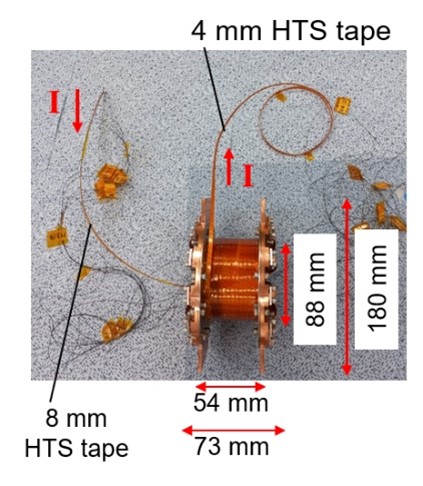
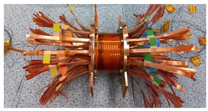
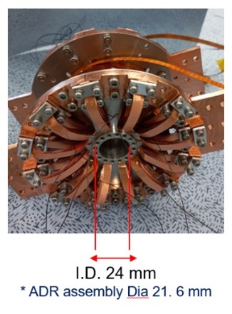
This presentation will address a unique cooling strategy of superconducting magnet for CADR (Continuous Adiabatic Demagnetization Refrigerator) applications. The magnet is to magnetize and demagnetize the magnetocaloric material in CADR up to a few Tesla during its refrigeration cycle period. The continuous operation of ADR (Adiabatic Demagnetization Refrigerator) is particularly challenging because the superconducting magnet inherently may generate significant AC (alternating current) loss during the fast ramping processes. In the CADR, the magnet is conduction-cooled by a typical two-stage Gifford-McMahon or pulse tube cryocooler that can keep the magnet temperature sufficiently low, but the cooling capacity of the cooler is always limited especially at 5 K range. For a stable ramping operation of the magnet, we proposed to insert the thermal drains that are made of Oxygen-Free High Conductivity (OFHC) copper in the winding pack for fast thermal diffusion to the heat sink. Each thermal drain aligned in an axial direction of the magnet has a width of 6 mm and a thickness of 50 μm with good thermal contact to the superconductor. The exemplary HTS solenoid is fabricated to produce the alternating 0 to 4 T magnetic field for the ADR and cooled at 5 K. The AC loss of the magnet (a solenoid with 112 layers each of which consists of 12 turns of the conductor in a layer-winding configuration) is estimated as 0.4 W with the ADR cycle period of 80 seconds and verified with the ramping rate of 0.1 T/s, which results in the successful operation without quench. The thermal analysis also ensures the temperature of the conductor to remain below 20 K during the experimental condition. Based on the results of the thermal analysis, we realize that it is also possible to design an LTS coil for CADR because the hysteresis AC loss of NbTi wire is smaller than that of typical 2G-coated HTS tape. In comparison to the 4-mm wide surface of HTS tape, a multifilamentary LTS wire with a few μm filament diameter is quite advantageous to reduce the overall hysteresis AC loss of the conduction-cooled magnet. This paper discusses three primary factors of the magnet design and its operation that determine the relative adequacy of HTS or LTS for CADR; heat generation due to AC loss, thermal contact consideration, and magnet volume with the safe current-sharing temperature. We will present the selection criteria of HTS or LTS magnet for CADR in terms of the safe magnet operating temperature for the efficient ADR cycle time period which determines the overall cooling power of the refrigerator. The stable fast-ramping operation of the conduction-cooled superconducting magnet is an enabling technology for developing an efficient sub-Kelvin CADR and ultimately a compact sub-Kelvin refrigerator.
Fig. Fabricated HTS magnet for fast ramping operation; (a) Initial layer winding structure (b) Completed winding with copper strip thermal drains (c) Magnet assembly with final thermal drains anchored to the magnet flange.
AP7-5
Dynamo flux pumps at Robinson
14:15-14:30 Dec.5
*Adam C Francis1, Dominic A Mosely1 and Rodney A Badcock1
Paihau-Robinson Research Institute, Victoria University of Wellington, 76 Sydney St, Lower Hutt, Wellington, 5012, New Zealand1
High temperature superconducting (HTS) electromagnets consisting of one or more HTS tapes wound into a coil are becoming the go to technology for applications that require high magnetic fields [1]. These coils require high current supplies which are generally large Copper (Cu) based power supplies with Cu leads/bus bars that feed directly into the cryogenic environment, resulting in a large thermal load [2]. An alternative to Cu power supplies and their large leads are superconducting power supplies, also known as ‘flux pumps’[3]. These superconducting power supplies have the advantage of being constructed from superconducting materials allowing them to be smaller in volume and weight and to exist in the same cryogenic environment as the HTS magnet. What’s more, the feedthroughs required to power these superconducting power supplies are small, leading to a greatly reduced thermal load on cryogenic systems when compared to Cu current leads. Finally, the ohmic losses incurred from Cu leads are non-existent in these superconducting supplies, meaning much lower driving voltages are required to maintain high currents in a HTS load coil. Superconducting power supplies are separated into two categories: Dynamo and Transformer rectifier. Paihau - Robinson Research Institute is a world leader in the research of both types.
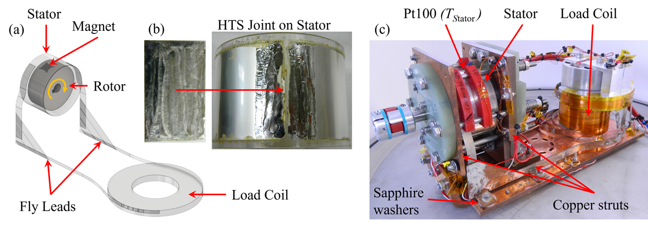
In this presentation the findings of a recently published letter [4] in Applied Physics Letters will be exhibited, in which we introduced a dynamo capable of outputting DC currents greater than 1 kA into a superconducting load. This dynamo utilizes a continuous cylindrical stator and a single permanent magnet on a rotor to generate this current. The continuous stator design of this dynamo results in an absence of edge effects which usually dominate the output voltages in single and multiple tape dynamos, thus allowing for direct observations of the driving mechanism. The stator temperature and rotor frequency responses were studied over the ranges of 30 – 100 Kelvin and 9 – 25 Hz respectively. Additionally, the dynamo was simulated with finite element modeling using T-A formulation based around the experimental apparatus dimensions and the measured characteristics of the stator material for both temperature and applied perpendicular magnetic field (B⊥). These findings show that the output voltage of dynamos is due to the circulating currents in the superconductor interacting with the non-linear resistance of type-II superconductors in the presence of a moving B⊥, providing further experimental evidence in support of the findings made by Matiara et al. a few years prior[5, 6]. Additionally, this work shows that as the stator temperature of a dynamo decreases, so too does its output voltage due to flux screening, demonstrating that multi kA dynamos should be operated well above the flux screening temperature of the stator. This working design is now being implemented into an ‘L-zero’ dynamo for space applications, addressing the problem of rotational inertia whilst supplying a DC output voltage. This is being done by utilizing two identical rotors which rotate in opposite directions at the same speed combined with two cylindrical continuous stators connected in parallel to the load.
This presentation will also touch on the breadth of dynamo research currently being pursued at Paihau – Robinson Research Institute by showcasing two further studies. One, a comparative study where open circuit voltages from various commercially available ReBCO tapes are compared directly using a rotor bathed in liquid nitrogen. The results of this study will influence future dynamo design by highlighting the differences between HTS manufacturer offerings when using their products as dynamo stators. Two, a HTS wafer dynamo where a B⊥ is moved in a circular motion about the centre of a disk of HTS material attached to a sapphire plate. This disk is then connected to a superconducting load via HTS tapes soldered to the centre and rim of the disk.
1. Zhou, Y.-H., D. Park, and Y. Iwasa, Review of progress and challenges of key mechanical issues in high-field superconducting magnets. National Science Review, 2023. 10(3).
2. Geng, J., C.W. Bumby, and R.A. Badcock, Maximising the current output from a self-switching kA-class rectifier flux pump. Superconductor Science and Technology, 2020. 33(4): p. 045005.
3. Wen, Z., H. Zhang, and M. Mueller, High Temperature Superconducting Flux Pumps for Contactless Energization. Crystals, 2022. 12(6): p. 766.
4. Venuturumilli, S., et al., Temperature dependent behavior of a kA-class superconducting flux pump with a continuous cylindrical stator. Applied Physics Letters, 2023. 123(20): p. 202601.
5. Mataira, R.C., et al., Origin of the DC output voltage from a high-Tc superconducting dynamo. Applied Physics Letters, 2019. 114(16): p. 162601.
6. Mataira, R., et al., Mechanism of the High-$T_c$ Superconducting Dynamo: Models and Experiment. Physical Review Applied, 2020. 14(2): p. 024012.
This work was supported by funding from the Ministry of Business, Innovation and Employment, New Zealand under Contract Nos. RTVU2004 and RTVU1707.
Figure 1. Continuous stator dynamo. (a) A CAD model showing the superconducting circuit inclusive of the dynamo rotor and magnet. (b) The stator and lap joint HTS pieces tinned and ready to be soldered together mounted on a sapphire cylinder former. (c) The completed system constructed and mounted to a cold head.
Keywords: HTS power supply, Flux Pump, Dynamo, High current
AP7-6
Long-range measurement experiment with all-optical cryogenic liquid level sensor
14:30-14:45 Dec.5
*Toshiyuki Oikawa1, Kodai Yasuda1, Muneo FUTAMURA1, Shigeo Miura1, Hiroshi Okamoto1
Akita Prefectural University1
1. Introduction
Liquid hydrogen could potentially be used as a coolant for superconducting cables for electrical power transmission [1]. In addition, hydrogen is a candidate for energy storage in the current shift to renewable energy.
Liquid level gauges are needed to manage liquid hydrogen. Existing liquid level gauges for liquid hydrogen tend to have components and electrical wiring in contact with the liquid. This poses problems of liquid loss due to heat transfer and potential accident risk due to a surge current etc.
We are developing an all-optical, completely non-contact liquid level sensor for liquid hydrogen that does not use electrical wiring in the container. Previously [2], we performed an experiment using liquid nitrogen with the distance between the level sensor and the liquid surface being ≈ 30 cm. Here we report on an experiment, wherein the distance is increased to ≈ 1 m.
2. Principle of measurement
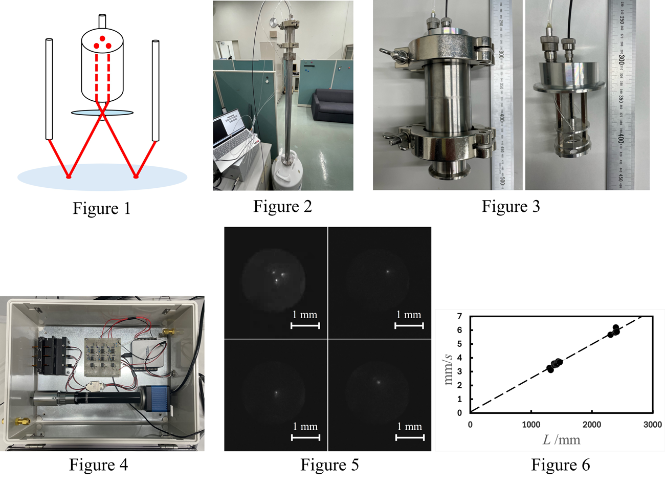
The measurement principle is shown in the Fig. 1. The liquid level sensor consists of three optical fibers, a fiber bundle, and a lens. When light is irradiated onto the liquid surface from the tips of the three optical fibers, the image reflected on the surface of cryogen is formed on the end surface of the fiber bundle through the lens. The reflected image is a triangle of three light points, and the size of the triangle is a function of the liquid level.
When the liquid surface is not still, the three light points also move around and they could overlap each other, making it difficult to observe the triangle. Therefore, the position of each light point and the size of the triangle can be obtained by observing the reflection image of each light point one at a time and averaging the multiple observation data.
3. Experiment
Figure 2 shows an overall view of the experimental equipment. We used liquid nitrogen for this study, and an experiment using liquid hydrogen is underway. The 1.0 m long tube for a long-range measurement was placed at the mouth of the liquid nitrogen tank, and the liquid level sensor was placed on top of the tube.
Figure 3 shows the liquid level sensor. The liquid level sensor consists of three optical fibers, a fiber bundle, a lens to focus the reflected image, and a lens to focus the light irradiated on the liquid surface. A KF50 flange and a KF50-KF40 reducer are connected to the liquid level sensor. This allows us to connect the sensor to a KF40 flange on a glass dewar for liquid hydrogen.
Figure 4 shows an experimental box. When conducting experiments using liquid hydrogen, electronic devices such as cameras need to be placed inside a box that is filled with nitrogen to prevent contact between the electronic devices and hydrogen. A camera (pco.panda) for observing reflected images, an irradiation coupler, an irradiation control circuit, and an interface (NI USB-6002) to a PC are placed inside the box. In observations of reflected images, the intensity of light is inversely proportional to the square of the distance, making it difficult to observe the reflected image when measuring over long distances. Therefore, a high-sensitivity camera that can observe the reflected image is used. The irradiation manifold consists of an optical fiber tip, a lens, and a semiconductor laser to provide a stable light beam to the optical fiber. The semiconductor lasers are connected to a PC through an irradiation control circuit and interface and are programmed to blink in sequence using a Python program.
4. Experimental results
Figure 5 shows an observed reflection image. The reflection image is part of a movie that was saved as a frame-by-frame image using movie editing software. Since the video is 60 FPS, the image acquisition rate is approximately every 0.017 s. The semiconductor lasers are repeatedly turned on for 0.1 s and then turned off for 0.1 s. Therefore, it is possible to save 5 to 6 images of the reflection of each light point out of the three light sources. The position of each light spot is determined from these observed images by image processing. First, we compute the difference between the image with the light spot and the image without the light spot. We then detect objects by removing signals below a threshold value, and then compute the center of gravity of the remaining signal. This operation is performed on multiple images, and the average of the center of gravity is obtained. The coordinates of this average are considered to be the center coordinates of the light point. In this way, the center coordinates of each of the three light points is obtained, and the distance between the light points is calculated.
Figure 6 plots the distance L between the liquid surface and the sensor against the distance between the light spots on the acquired images. In this experiment, two 1.0 m tubes were used, and measurements were made at distances of L = 1300 mm ~ 1500 mm and L = 2300 mm ~ 2500 mm.
An approximate straight line was obtained from the measurement results, and the RMS value of the horizontal misalignment was determined to be 52.6 mm. This value is considered to be the measurement accuracy.
5. Future Tasks
The center coordinates of the light point obtained this time are the coordinates obtained from the data observed when the liquid surface was stationary. We plan to extend our experiment to cases wherein the liquid surface is not still.
In addition, measurements using liquid hydrogen are underway.
AP7-7
Progress on a demonstration mission operating an ion thruster magnet on the International Space Station
14:45-15:00 Dec.5
*Nicholas Long1, Jakub Głowacki1, Max Goddard-Winchester1, Sebastian Hellmann1, Xiyong Huang1, Ben Mallett1, Jamal Olatunji1, Betina Pavri1, Cameron Shellard1, Nicholas Strickland1, Emile Webster1, Avinash Rao2, David Wright3, Tulasi Parashar4, Randy Pollock1
Paihau - Robinson Research Institute, Te Herenga Waka - Victoria University of Wellington, Wellington, New Zealand1
IDS Consulting, Auckland, New Zealand2
David Wright, Asteria Engineering Consultancy, Christchurch, New Zealand3
School of Physical and Chemical Sciences, Te Herenga Waka - Victoria University of Wellington, Wellington, New Zealand4
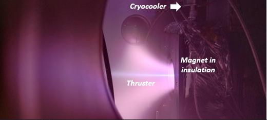
Operating superconducting magnets in space presents unique challenges in cooling and charging within constrained energy and thermal budgets. Construction of a flight model HTS magnet is well advanced for delivery to the International Space Station. The magnet will operate on the Nanoracks External Platform (NREP) of the Japanese experiment module Exposed Facility (JEM-EF). The magnet consists of four double-pancake HTS REBCO coils with a warm bore of 52 mm. It is intended to approximate the magnet design suitable for Applied-Field magneto plasma dynamic (AF-MPD) ion thruster systems. We have operated the magnet at approximately 0.9 T during laboratory testing at 75 K. Current to the magnet of up to 30 A is supplied by a flux pump which minimizes the total thermal load. The magnet has achieved the same field pre and post vibration testing giving us confidence launch vibrations will not induce degradation. The experiment will incorporate two TimePix radiation sensors to measure the influence of strong magnetic fields on charged radiation incident on the space station.
This mission is part of a larger development program on Applied Field – Magneto-plasma-dynamic (AF-MPD) ion thrusters. We will show some early laboratory results from a larger bore and higher field magnet coupled to an in-house designed AF-MPD thruster demonstrating the advantages of higher fields in increased thruster efficiency and thrust density.
This work was funded by the New Zealand Ministry of Business, Innovation and Employment contract numbers RTVU2003 and RTVU1916.
Figure 1. Applied field magneto-plasma-dynamic thruster in operation.
Keywords: HTS magnet, applied-field MPD, ion thruster, space
AP7-8
Improvement of measurement accuracy by detailed understanding of electromagnetic and thermal conduction phenomena in AC loss measurement equipment based on mechanical input
15:00-15:15 Dec.5
*Satsuki Okumura1, Koki Okubo2, Yutaka Terao1, Shuichiro Fuchino1, Hiroyuki Ohsaki1, Keiichi Okai3, Hideyuki Taguchi3
University of Tokyo, Graduate School of Frontier Sciences, Kashiwa, Chiba, 277-8561 Japan1
University of Tokyo, Graduate School of Engineering, Bunkyo-ku, Tokyo, 113-8656 Japan2
Japan Aerospace Exploration Agency, Chofu, Tokyo, 182-0012 Japan3
There has been a worldwide rush to solve environmental and energy problems in recent years. In particular, the development of high-efficiency, high-power-density rotating machines has been active in the transportation and energy fields. Fully superconducting rotating machines (FSRMs), which have superconducting field and armature windings [1] attract attention because they achieve high efficiency and high-power density. We have been studying the FSRM using REBCO wire for the field windings and MgB2 wire for the armature windings [2].
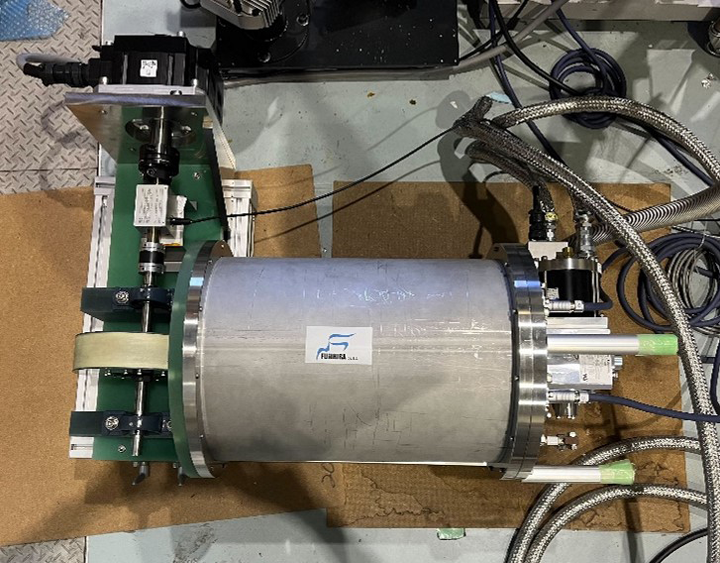
AC losses, hysteresis and coupling losses, are generated because a rotating magnetic field is applied to the armature windings. It is very important to develop a FSRM to investigate the magnitude and causes of this AC loss in detail. Therefore, we have experimentally measured the AC loss in MgB2. Figure 1 shows the AC loss measurement equipment based on mechanical input. MgB2 coil is placed inside the cryostat. A rotating magnetic field is applied to the MgB2 coil by rotating a Halbach array of permanent magnets outside the cryostat. Temperature sensors are attached to the MgB2 coil so that we can measure the temperature at some parts of the MgB2 coil. It is necessary to consider the electromagnetic phenomena and heat generation by AC losses in the measurement equipment.
This study aims to improve measurement accuracy by a detailed understanding of electromagnetic and thermal conduction phenomena in AC loss measurement equipment based on mechanical input. We use multiple temperature sensors to evaluate the temperature distribution. By comparing two types of wire with the same diameter, number of filaments, and filament diameter but different twist pitches (25 mm and 100 mm), the relationship between the magnitude of AC loss and temperature gradient due to twist pitch is clarified.
[1] Yutaka Terao, Satsuki Okumura, Hiroyuki Ohsaki, “Study on Electric and Magnetic Loadings in Fully Superconducting Motor Design,” Physica C: Superconductivity and its Applications, vol. 617, 1354399, 2024.
[2] Yutaka Terao, Haruka Nakamura, Satsuki Okumura, Shuichiro Fuchino, Hiroyuki Ohsaki, “AC Loss of MgB2 Superconducting Coils with Alternating Transport Current in Rotating magnetic Field,” IEEE Transactions on Applied Superconductivity, vol. 33, no. 5, pp. 1-5, Aug. 2023.
Figure 1. The AC loss measurement equipment based on mechanical input
Keywords: MgB2, AC loss, thermal conduction phenomena
AP7-9
High temperature superconducting magnet with persistent current mode based on REBCO tapes
15:15-15:30 Dec.5
*Fazhu Ding, Hongwei Gu
Institute of Electrical Engineering, Chinese Academy of Sciences
Developing closed-loop magnets that operate in persistent current mode (PCM) is crucial for achieving higher resolution and sensitivity in NMR and MRI devices. Here, we report the world’s first closed-loop multi-pancake (MP) HTS magnet operated in PCM based on a novel jointless winding method and superconducting joint of REBCO coated conductors (CCs), to the best of our knowledge. The in-field characteristics of the CC and the joint are investigated to determine the operating parameters of the magnet. The central field of the magnet reaches ~0.4 T at 77 K, with a drift rate of ~1.1Í10-3 ppm/h, inferring that the joint resistance can be less than 3.1Í10-14 Ω. Furthermore, although the _I_cvalue of the joint is considerably lower than that of the CC at self-field, it can maintain similar comparable or even higher in-field _I_ccompared to the CC, which is immensely beneficial for magnet applications. This study provides valuable insights into the design and construction of the closed-loop MP magnets operating in PCM.
